Inside the IBLDC Motor: How It’s Made and Why It Matters
When you hear “IBLDC motor,” you might picture a sleek, high‑efficiency drive humming inside a drone or an electric scooter. The reality is a lot more fascinating: a carefully choreographed series of steps, each designed to coax magnetic fields into precise motion. Understanding the IBLDC motor manufacturing process reveals why these motors dominate applications that demand power‑to‑weight excellence.
What Sets an IBLDC Motor Apart?
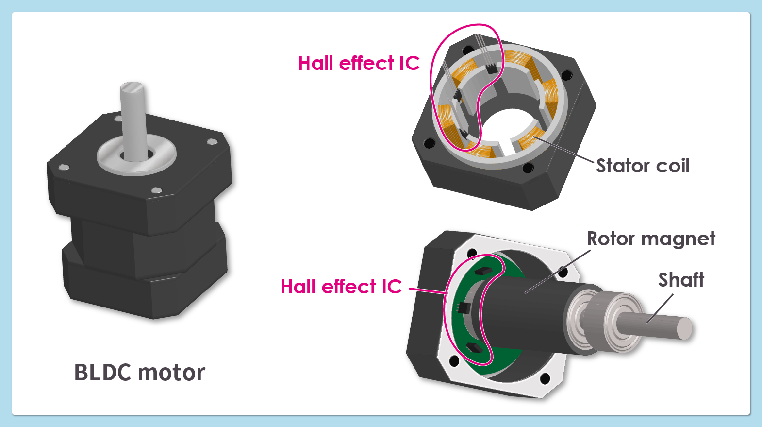
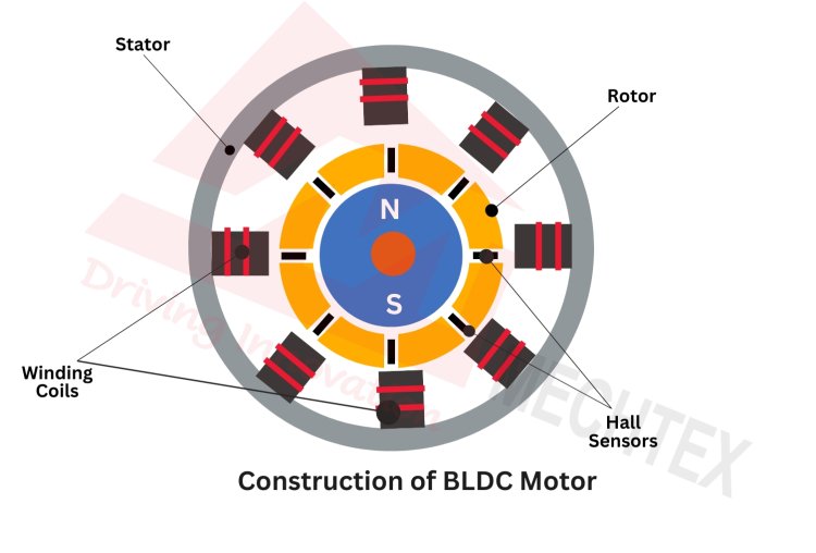
IBLDC stands for “inner‑brushless DC.” Unlike traditional brushed motors, the IBLDC design hides the permanent magnets inside the rotor, while the stator carries the windings. This layout reduces exposure to dust and debris, lowers friction, and extends lifespan. The inner placement also enables tighter air gaps, which translates into higher torque density—a key selling point for aerospace, robotics, and portable devices.
Step‑by‑Step Look at the IBLDC Motor Manufacturing Process
From raw metal sheets to a finished motor ready for integration, the journey can be broken down into six core stages. Each stage blends automation with hands‑on craftsmanship, ensuring the final product meets exacting performance standards.
1. Design and Simulation
Engineers start in a CAD environment, defining geometry for the stator core, rotor laminations, and magnet placement. Advanced finite‑element analysis (FEA) predicts magnetic flux paths, heat distribution, and mechanical stresses. Iterations are rapid: a tweak to tooth width or magnet angle can shave off watts of loss without a physical prototype.
2. Material Selection and Procurement
The stator core typically uses silicon‑steel laminations, each a fraction of a millimeter thick to curb eddy currents. For high‑performance models, manufacturers may opt for amorphous steel or even powdered iron. Permanent magnets are usually neodymium‑iron‑boron (NdFeB) with a protective coating to resist corrosion. The choice of copper wire for windings balances conductivity against size and cost.
3. Lamination Stamping and Stacking
Large presses stamp the silicon‑steel sheets into the characteristic “U” or “V” shaped teeth that will become the stator’s magnetic path. These stamped pieces are then stacked, aligned, and bonded—often using a resin‑impregnation process that fills microscopic gaps and adds rigidity. The resulting stack is a solid core ready for winding.
4. Winding the Stator
Automated winding machines feed insulated copper wire around the stator teeth in precise patterns—typically a three‑phase, double‑layer configuration. Tension control is critical; too loose and the coils vibrate, too tight and the insulation can scar. After winding, the coils undergo a curing cycle that sets the epoxy resin, locking the wire in place.
5. Rotor Assembly and Magnet Insertion
Rotor laminations follow a similar stamping and stacking routine, but the key difference is the insertion of the permanent magnets. Magnets are placed into machined pockets on the rotor surface, then a retaining ring or adhesive secures them. Because the magnets sit inside the rotor, the assembly must be perfectly balanced to avoid wobble at high speeds.
6. Final Assembly, Balancing, and Testing
With stator and rotor ready, the motor is brought together in a clean‑room environment. Bearings are pressed onto the shaft, and the housing is sealed—often with a vented design that lets heat escape while keeping contaminants out. Dynamic balancing machines spin the motor to detect and correct any mass irregularities. Finally, a suite of tests—no‑load run, load‑torque mapping, thermal imaging, and vibration analysis—verifies that the motor meets its design specs.
Quality Checks That Keep the Motor Running Smoothly
Even after the mechanical steps are complete, quality assurance continues. Electrical insulation tests, such as hipot testing, confirm that winding insulation can withstand high voltages without breakdown. A “burn‑in” phase runs the motor at elevated temperatures for several hours, coaxing out early‑life failures. Statistical process control (SPC) charts track key parameters—winding resistance, magnet strength, and bearing preload—so any drift is caught before a batch ships out.
Why the Manufacturing Story Matters to End Users
For engineers selecting a drive solution, the inner details of the production line translate into tangible benefits: higher efficiency, lower maintenance, and tighter packaging. A well‑balanced rotor reduces acoustic noise—a subtle but important factor in consumer electronics. And robust testing means the motor can survive the thermal cycles of a solar‑powered UAV without degrading.
Frequently Asked Questions
- What’s the main advantage of the “inner” brushless design? By nesting the magnets inside the rotor, the motor enjoys better protection from external contaminants and can achieve a smaller air gap, which boosts torque density and overall efficiency.
- Can I customize an IBLDC motor for a specific application? Yes. Manufacturers often offer variations in winding count, magnet grade, and housing material, allowing designers to trade off between speed, torque, and thermal performance.
- How do manufacturers ensure the motor stays balanced at high RPM? After assembly, the motor undergoes dynamic balancing on a precision spindle. Any detected imbalance is corrected by trimming material or adding micro‑weights until vibration stays within tight tolerances.
- Is the manufacturing process environmentally friendly? Modern plants recycle steel laminations, use low‑VOC epoxy resins, and implement energy‑recovery systems on stamping presses. Additionally, the high efficiency of IBLDC motors contributes to lower energy consumption over the product’s lifespan.

![Explore Key Types of DC Motors & Their Uses [2026]](https://www.grwinding.com/wp-content/uploads/2025/01/Diagram-of-a-BLDC-motor-showing-stator-coils-and-rotor-magnets.webp)