How to Control Peltier Elements: A Practical Guide
Whether you’re building a compact cooler for a laptop or a temperature‑stabilized chamber for a lab experiment, the key to success lies in how you control Peltier elements. These thermoelectric modules can pump heat with astonishing speed, but without proper regulation they can overheat, waste power, or simply fail to reach the desired setpoint. This guide walks you through the essentials—hardware, wiring, and software—so you can tame the heat‑pump effect with confidence.
Understanding the Basics of Peltier Modules
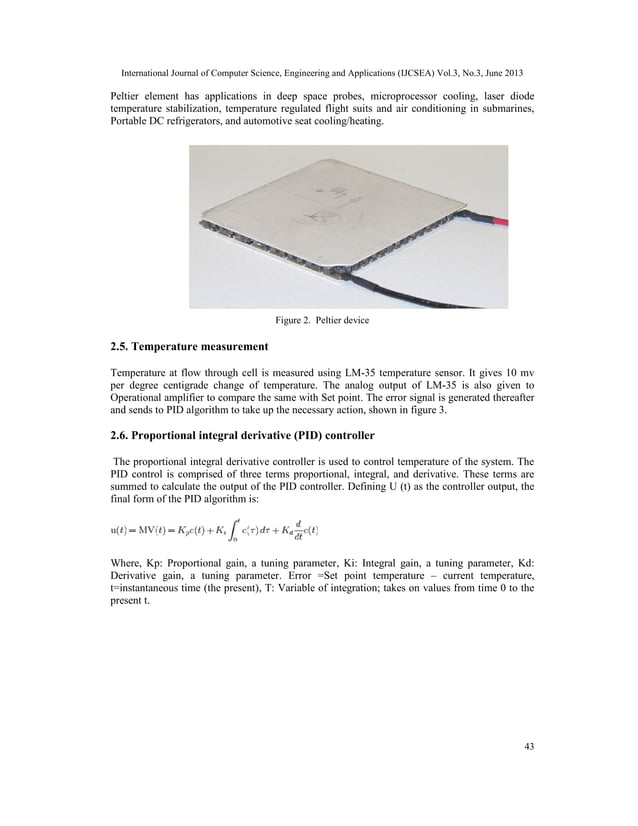
A Peltier element, also known as a thermoelectric cooler (TEC), consists of many semiconductor couples sandwiched between two ceramic plates. When a DC current flows, one side becomes cold while the opposite side heats up. The amount of heat moved is roughly proportional to the current, but the relationship isn’t perfectly linear because the device’s internal resistance changes with temperature.
Because the hot side must dissipate the pumped heat plus the Joule heating generated by the current, a good heat sink is non‑negotiable. Ignoring this can lead to thermal runaway, where the module quickly reaches its maximum temperature and shuts down.
Why Precise Control Matters
In many projects the goal isn’t just “make it cold,” but “maintain a specific temperature.” Without feedback, a Peltier will either overshoot (causing condensation) or undershoot (failing to cool enough). Precise control also improves efficiency: by matching the current to the actual heat load, you reduce wasted power and extend the lifespan of both the module and the power supply.
Choosing the Right Power Supply
Most TECs operate between 12 V and 24 V, drawing anywhere from a few hundred milliamps to several amps. A regulated, low‑ripple supply is essential; cheap unregulated adapters can introduce noise that confuses the control loop. If you anticipate varying loads, consider a supply with programmable voltage or current limiting.
Driving the Module: Voltage vs. PWM
Two common approaches exist:
- Direct voltage control: Set a constant voltage that matches the desired current. Simpler, but less flexible when the load changes.
- PWM (pulse‑width modulation): Switch the supply on and off rapidly, adjusting the duty cycle to control average power. PWM lets you keep the voltage high—good for fast response—while still limiting heat.
When using PWM, a high‑frequency driver (typically 10–20 kHz) minimizes audible whining and reduces the risk of inductive spikes that could damage the microcontroller.
Adding Temperature Feedback
Thermistors, silicon diode sensors, or miniature RTDs are the usual suspects for measuring temperature. Place the sensor as close as possible to the cold side, ideally embedded in a thermal paste layer to improve contact. The sensor’s resistance or voltage output feeds into your controller, closing the loop.
Implementing a PID Controller
Proportional‑Integral‑Derivative (PID) control is the workhorse for most temperature‑stabilization tasks. The proportional term reacts to the current error, the integral term corrects accumulated offset, and the derivative term dampens overshoot. Tuning can start with the classic Ziegler‑Nichols method, then fine‑tune by hand for your specific load.
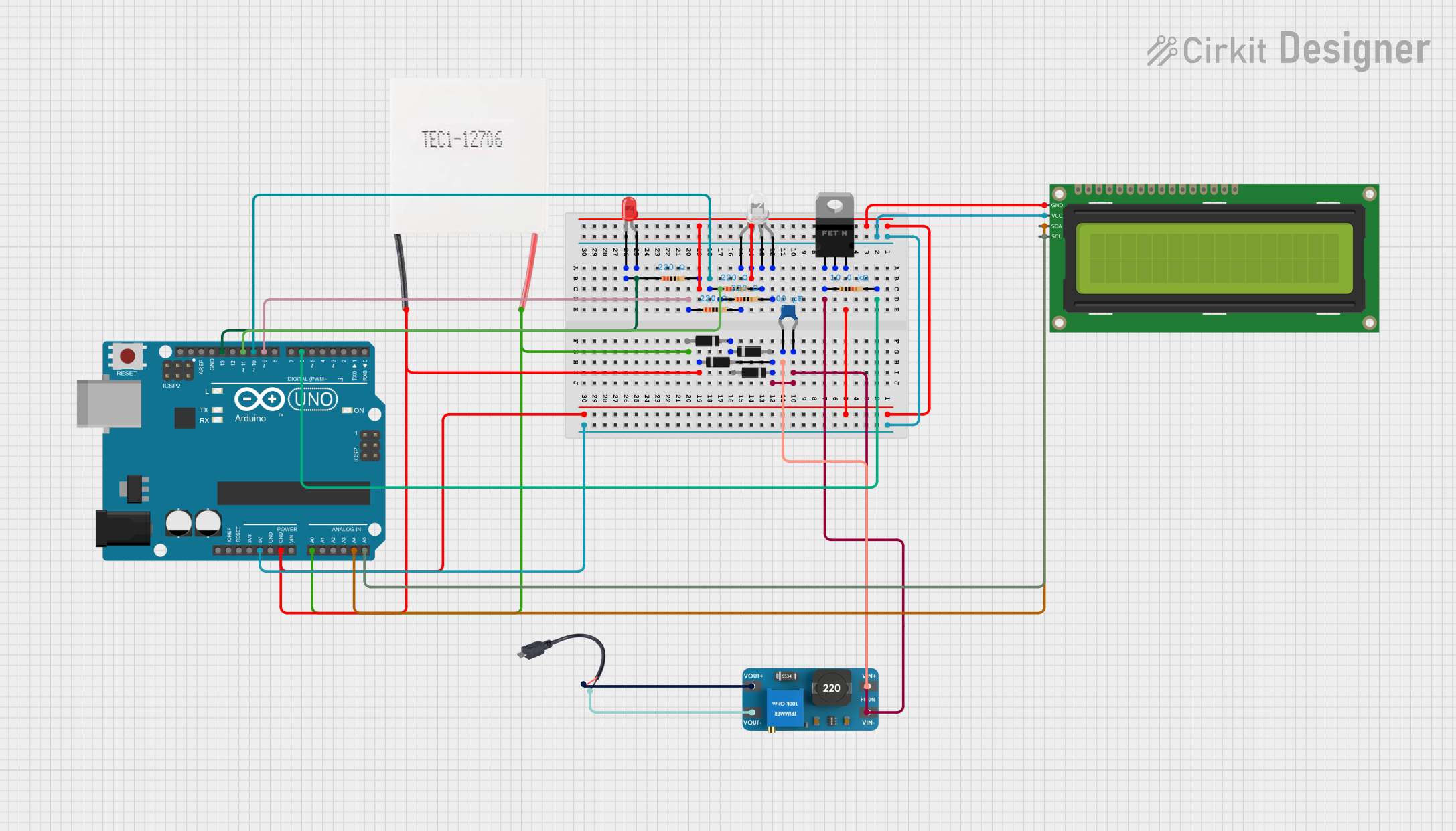
Many hobbyist boards—Arduino, ESP32, or Raspberry Pi Pico—have built‑in libraries that handle the math. Simply read the sensor, compute the PID output, and adjust the PWM duty cycle accordingly.
Wiring Tips to Keep Things Safe
1. Use a proper MOSFET or dedicated TEC driver rather than driving the module directly from a microcontroller pin. The MOSFET should handle the peak current with a comfortable safety margin.
2. Include a flyback diode across the TEC if you’re using a linear driver; this protects against voltage spikes when the current is abruptly interrupted.
3. Provide adequate heat sinking on the hot side, preferably with a fan or liquid‑cool loop. Thermal paste between the TEC and the sink improves conduction.
4. Mind the wiring gauge. High current demands thicker wires to avoid voltage drop and heating.
Software Strategies Beyond Basic PID
For applications that experience rapid load changes—like intermittent high‑power heating—consider adding a feed‑forward term that anticipates the required current based on known heat inputs. Some designers also implement safety cut‑offs: if the hot‑side temperature exceeds a threshold, shut down the module immediately.
Logging temperature and power data to an SD card or cloud service can help you spot trends and refine your controller over time. Visual dashboards make troubleshooting less of a guessing game.
Common Pitfalls and How to Avoid Them
Thermal lag. The sensor may read a temperature that lags behind the actual surface temperature, leading to oscillation. Mitigate this by placing the sensor as close as possible to the controlled surface and by using a lower PID derivative gain.
Power supply droop. When the TEC draws its peak current, the supply voltage can sag, causing the controller to think the temperature is higher than it is. A small capacitor bank near the module can smooth out these transients.
Condensation. If you drive the cold side below the ambient dew point, moisture will form and can short circuitry. Insulating the cold side or using a sealed enclosure with desiccant solves most issues.
Testing and Calibration
Before integrating the system into a final product, run a bench test. Record temperature vs. PWM duty cycle at steady‑state, then plot the curve to verify linearity. Use this data to adjust the PID coefficients for the most stable response.
Calibrate the temperature sensor against a known reference—like a calibrated thermometer—to ensure accuracy, especially if you need ±0.5 °C precision.
Brief FAQ
What voltage range is safe for most Peltier modules?
Most standard TECs operate comfortably between 12 V and 24 V. Always check the manufacturer’s datasheet for the maximum rated voltage and current, and never exceed those limits.
Can I use a linear regulator instead of PWM?
Yes, but linear regulation wastes power as heat and offers slower response. PWM is generally preferred for efficiency and finer control, especially when the load varies.
How do I prevent the hot side from overheating?
Combine a robust heat sink with active airflow, monitor the hot‑side temperature with a separate sensor, and program an automatic shutdown or power‑reduction routine if a safe threshold is crossed.
Is a microcontroller necessary for basic control?
Not strictly. A simple analog circuit using a thermistor and a comparator can provide on/off control, but a microcontroller gives you the flexibility of PID tuning, data logging, and remote monitoring.